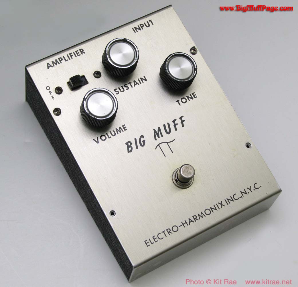
The Big Muff (π) is a fuzz/distortion effect pedal that has since the 1970s been one of the most influential guitar effects, being adopted by all sorts of musical genres and beloved by musicians worldwide. Originally the circuit was developed by Robert Myer of Bell Labs along with Mike Matthews of Electro-Harmonix, and the first units of the pedal were released in early 1969.
Nowadays Electro-Harmonix still sells the Big Muff and there have been several variations of the circuit throughout the years. Other effect pedal companies have also released their versions and interpretations of the Big Muff with their own modifications.
This article I’ll introduce the circuit and the parts which constitute it, and design and layout my out version, along with a PCB.
The following circuit is from a 72’ Triangle Big Muff, regarded by many players as one of the best sounding variations of the pedal:
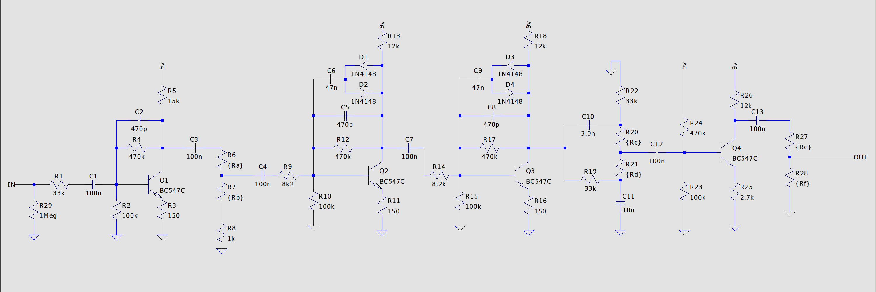
The circuit can be logically divided into 5 distinct sections, the input stage, the first and second clipping stages, the tone stack and the output stage.
Before we can do anything to the signal coming from the guitar, we need to amplify it given that usually the signal from a guitar is of high impedance. This is done by the input stage which is shown as follows:
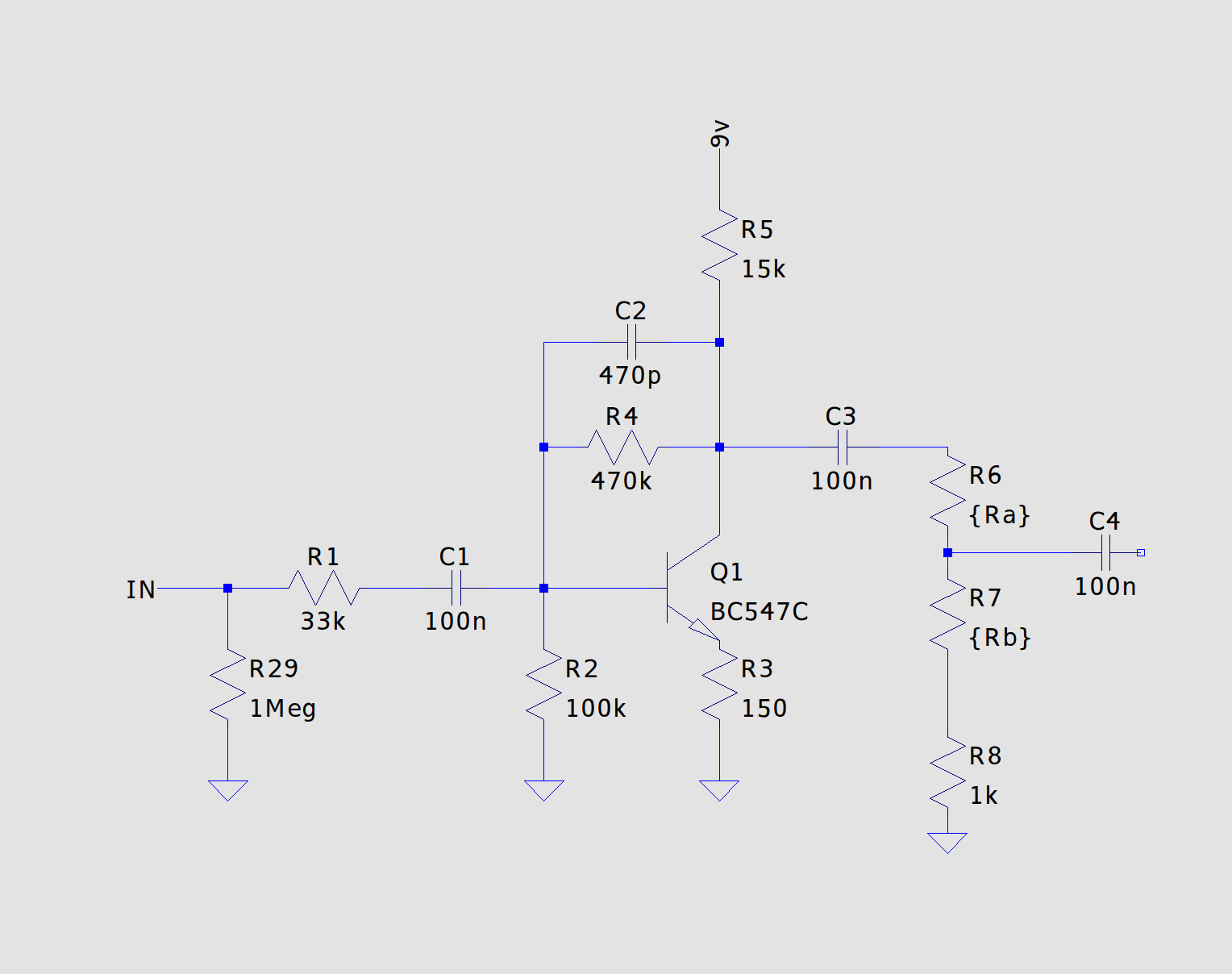
It is essentially a common emitter with series-shunt feedback amplifier, which provides better voltage gain stability, better frequency response and improved linearity when compared to a simple common emitter amplifier. R6 and R7 represent a 100kOhm linear potentiometer, which determine how much of the amplified signal passes on to the subsequent stage. Capacitor C1 forms a high pass filter and C2 is a miller capacitor forming a low pass filter while also preventing oscillation.
After getting amplified the actual distortion is achieved through the clipping stage. Each of the stages is almost identical to the input stage, the only difference being the diodes in the feedback loop. These will ‘clip’ the signal when a certain voltage threshold is reached, this is also referred to as soft clipping. The two copies of the circuit will guarantee that the desired effect is produced, if there was only one of these stages the big muff would sound more ‘overdrivy’.
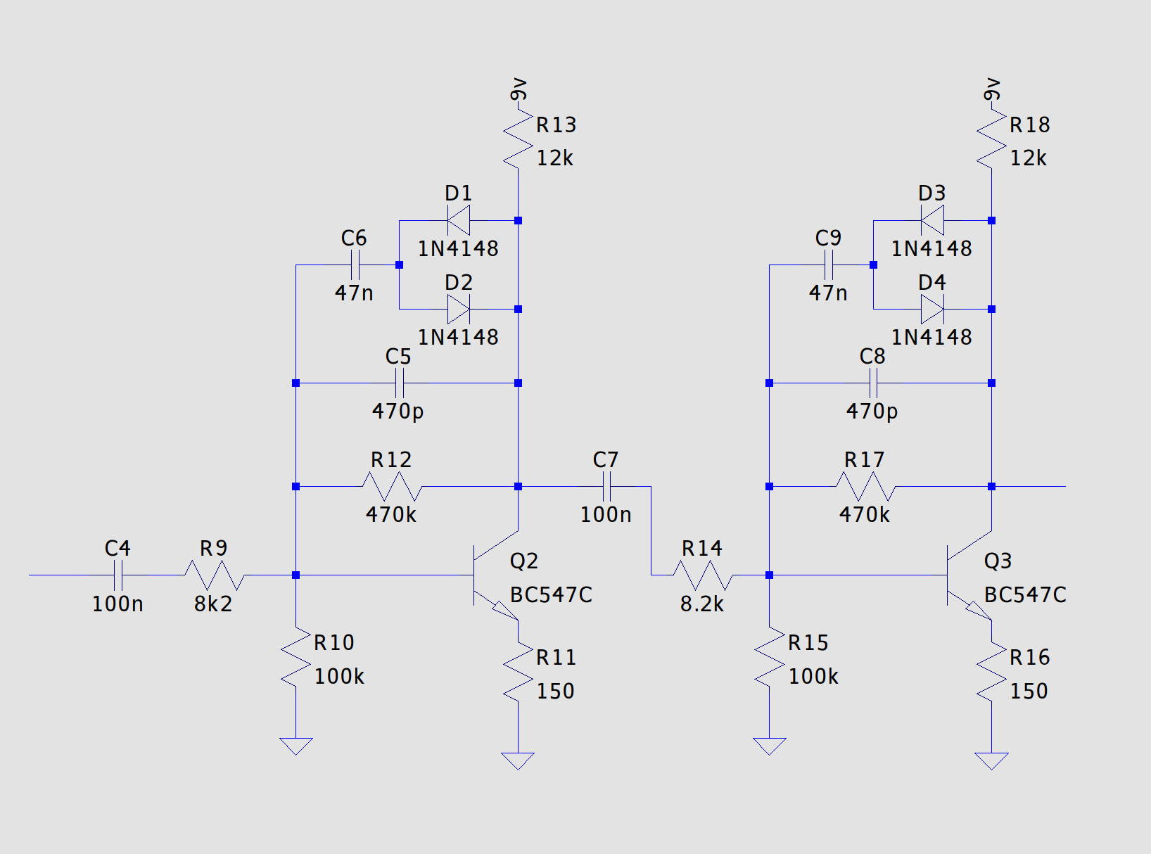
Replacing the clipping diodes on a Big Muff is a quick and easy way to change the way the pedal sounds.
After clipping the signal the tone stack is responsible for modifying the frequency content of the sound. The circuit is essentially mixture of a low-pass and a high-pass filter, resulting in the famous ‘mid-scoop’ that the Big Muff is known for.

C10 and R22 form an high-pass filter, and C11 and R19 for a low-pass filter, while R20 and R21 represent the 100kOhm linear potentiometer controlling the blend of both filters
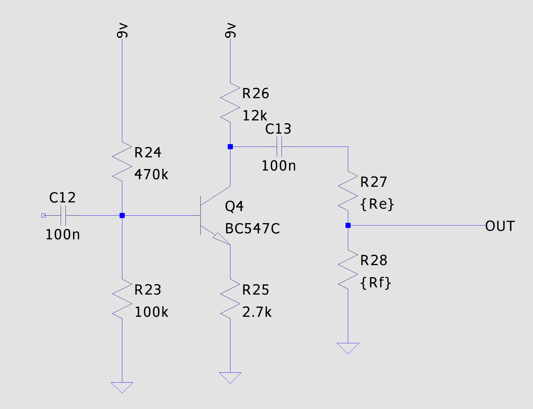
Finally the signal is amplified once again before leaving the pedal. The output stage consists of a simple common emitter amplifier and a potentiometer (a 100k lin. pot. once again, represented by R27 and R28).
Although the pedal is great by itself, many players usually will have a booster pedal alongside it while playing live, and engaging said booster during solo sections to allow their solo to ‘cut through the mix’. With this in mind I sketched out the following schematic in KiCad:
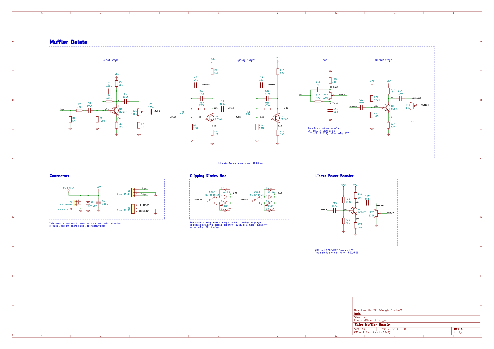
I’ve also added a DPDT switch to change the clipping diodes from a the usual silicon ones to LEDs. The PCB was also designed in KiCad:
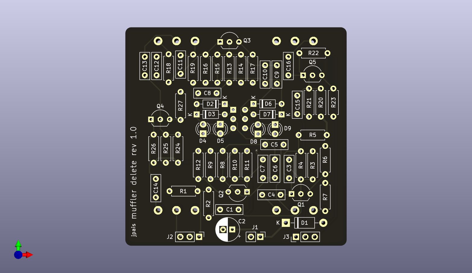

I left the inputs/outputs of the Big Muff circuit and the Linear Power Booster separated to allow more flexible wiring schemes. All the schematics and pcb files are available freely on my github page.